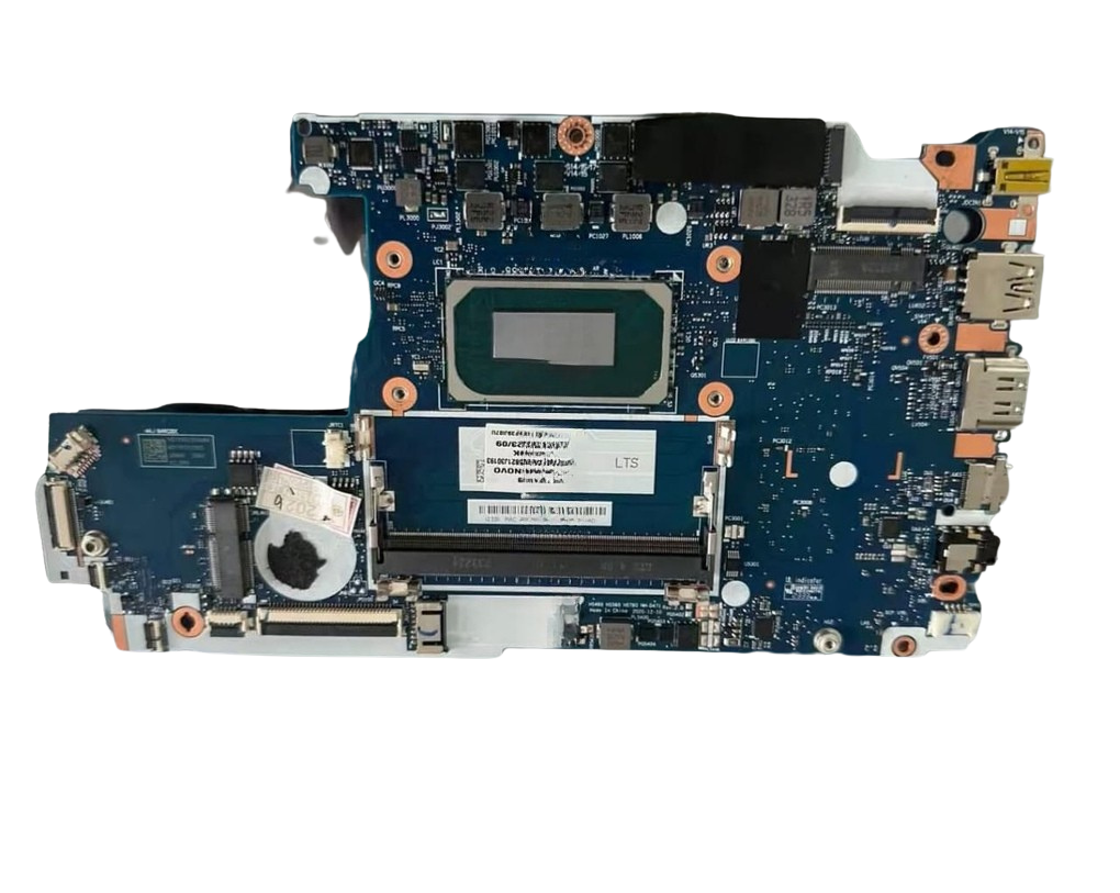
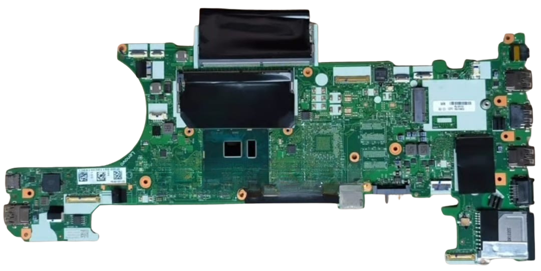
Laptop Computer Repairing Service
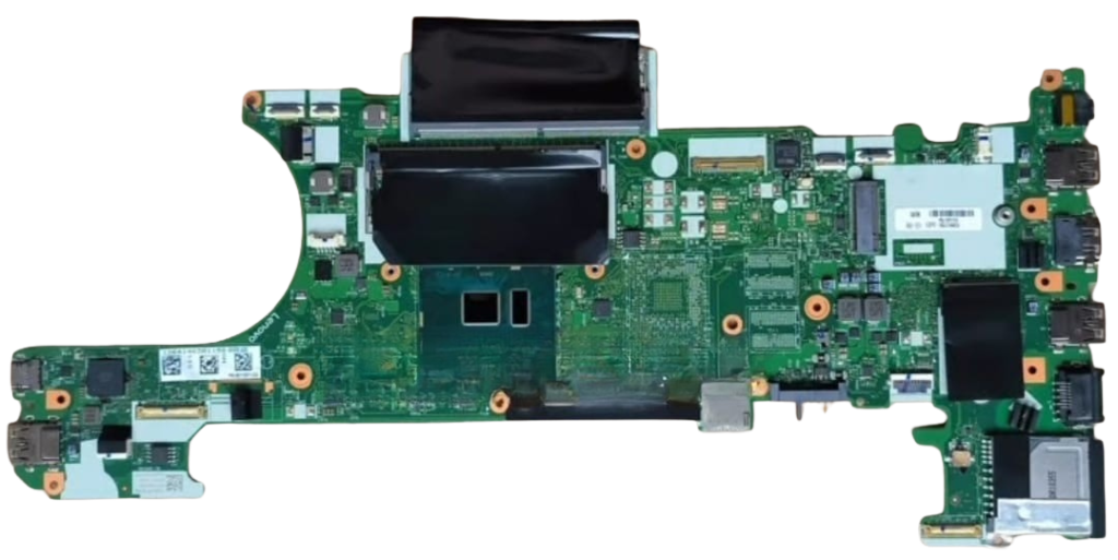
Motherboard spare parts replacement spans micro-soldered SMD components, integrated circuit (IC) controllers, and damaged physical interfaces.
High-Frequency Motherboard Spare Parts
Most board-level failures trace back to a specific set of active ICs, discrete power stages, and passive protective components.
| Component Category | Common Part Numbers / Types | Typical Symptoms When Faulty | Replacement Method |
| Charging ICs | BQ24780S, BQ24735, BQ25713, ISL88739, ISL95520 | Laptop will not charge, runs only on battery, or 19V rail stays at 0V. | Hot air de-soldering (QFN package) |
| 3.3V / 5V Step-Down ICs | TPS51225, RT8223, SY8286A, RT6256B | No standby LED, completely dead, missing 3.3V/5V rails. | Hot air gun (QFN / WQFN) |
| Power MOSFETs | N-Channel / P-Channel (e.g., AON7408, EMB09N03, 4407A) | 19V rail shorted to ground, burning smell, DC-IN over-current trips. | Micro-soldering iron / Hot air |
| Embedded Controllers (EC / SIO) | ITE (IT8586E, IT8987E), ENE (KB9012, KB9022), Nuvoton (NPCE285) | No response to power button, keyboard non-responsive, fan spins max speed. | Hot air + Pin programmer (for internal ROM) |
| SPI Flash BIOS ROM | Winbond (25Q64, 25Q128, 25Q256), Macronix (MX25L…) | Powers on with black screen, restarts every 5 seconds, slow boot. | SOIC-8 / WSON-8 rework + SPI programmer |
| SMD MLCC Capacitors | 10µF/25V, 22µF/25V (0805, 0603 packages) | Hard short on 19V B+ line ($0\,\Omega$ to ground). | Direct soldering iron replacement |
| DC-IN & I/O Ports | Type-C receptacles, barrel jacks, HDMI, USB-A 3.0 | Intermittent charging, physically broken pins, device not detected. | Through-hole & SMD soldering |
Component Sourcing & Compatibility Rules
When sourcing replacements from donor boards or electronic suppliers:
- MOSFET Matching:
- Match the Channel type (N-Channel vs. P-Channel).
- Ensure $V_{\text{DS}}$ (Drain-Source Breakdown Voltage) and $I_D$ (Continuous Drain Current) are equal to or higher than original specs.
- Verify $R_{\text{DS(on)}}$ (On-Resistance) is equal or lower to avoid excess heat generation.
- Capacitor Replacements:
- On the 19V input rail, use capacitors rated for 25V or higher (never substitute a 6.3V/10V cap from a CPU line onto a 19V line).
- On CPU/GPU core rails (low voltage, high capacitance), low-ESR tantalum or polymer caps must match capacitance rating ($\mu\text{F}$).
- Programmable SIOs:
- Chips like IT8586E and KB9012QF contain internal eFlash memory that must be programmed via dedicated JTAG/keyboard headers before the board will power cycle.
- Non-programmable SIOs (such as IT8528E or standard Nuvoton chips that read from the main BIOS SPI chip) only require exact part-number matching.
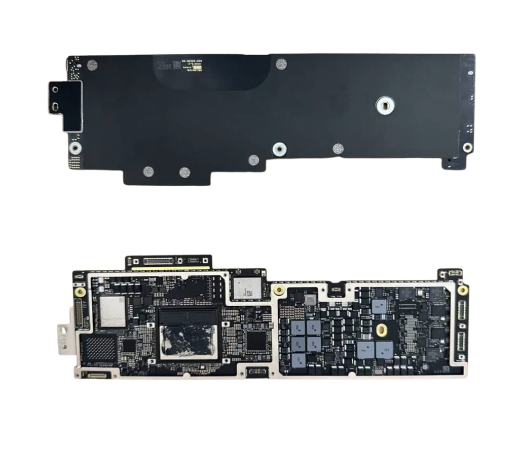
3. Repair Workflow & Quality Assurance
- Board Extraction & Thermal Pre-Heat:
- Clean conformal coating and flux residue with 99.9% Isopropyl Alcohol. Pre-heat multi-layer boards (especially high-copper ground planes) to 120°C–150°C to prevent PCB de-lamination and pad ripping during hot air rework.
- Micro-soldering & Solder Joint Inspection:
- Use high-grade rosin flux (e.g., NC-559 or equivalent). Inspect replaced IC alignment and solder bridges under a stereo-microscope.
- Post-Repair Impedance Test:
- Measure resistance to ground on all main power inductors (3.3V, 5V, RAM, VCORE) before applying bench power to confirm shorts are completely eliminated.
- Stress & Burn-In Testing:
- Run memory checks (MemTest86), FurMark/AIDA64 system stability tests, and full battery charge-discharge cycles for at least 1–2 hours before closing the chassis.